Technical Specifications
From a Google Ad to a Flight-Tested Frame
The Connection: Finding a Reliable Partner
The client first encountered KH Precision while researching high-end manufacturing partners via LinkedIn and specialised Google Search queries. After being targeted by a Google Ads campaign specifically highlighting our thin-wall machining capabilities, their engineering lead reached out.
We had been burned by local vendors who promised ±0.01 mm but delivered parts with visible chatter and internal stress warping.
Client engineering leadDespite the geographical distance, they decided to approach us with a “test batch” mindset — initially sceptical, but looking for a shop that could actually hold the specs.
Project Background: The “Weight vs. Stiffness” Dilemma
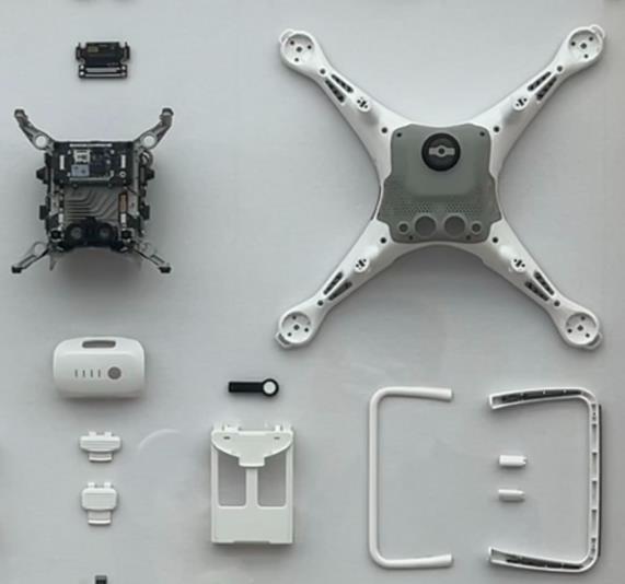
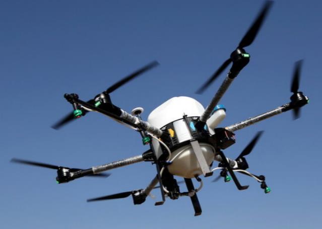
The project involved the Gen-3 “Atlas” heavy-lift drone. Previous iterations suffered from harmonic vibration during high-speed flight, which interfered with the LIDAR sensor accuracy. The structural frame needed to be light enough for a 45-minute flight time, but stiff enough to withstand the torque of high-KV industrial motors.
Our Immediate Response & Technical Roadmap
Upon receiving the 3D STEP files, our engineering team did not just generate a quote. We performed a Design for Manufacturing (DFM) review and identified that the 1.8 mm thin-wall arm sections would likely warp if machined with standard clamping.
Our strategy:
- Stress Management: we proposed a staged material removal process — roughing, followed by a 24-hour stress-relief cycle, before the final finish pass.
- Custom Fixturing: we engineered dedicated vacuum chucks to distribute clamping pressure evenly, preventing the “spring-back” effect common in aerospace-grade 7075-T6.
- 5-Axis Logic: to maintain the angular relationship between the motor mount and the main chassis, we determined the part must be finished in a single setup on our Haas UMC-750.
Project Challenges & Value-Added Cost Reduction
The primary challenge was the internal pocketing of the gimbal housing, which featured complex compound curves. To help the client scale without exhausting their R&D budget, we suggested a Hybrid Processing approach. By changing non-critical internal fillets from R0.5 to R1.5, we allowed larger diameter cutters to run at higher feed rates, reducing machining time (and cost) by 18% without impacting the structural integrity or weight.
From CAM Programming to Final Inspection
Our CNC programmers utilised Mastercam to develop high-speed trochoidal milling paths, minimising heat transfer to the workpiece.
- Timeline: first articles were completed in 5 days; the full batch of 20 sets was shipped within 12 working days.
- Quality Assurance: every critical datum was verified using a Hexagon CMM. We provided a full dimensional report (FAI) and material mill certificates (Cert 3.1) for every component.
- The Result: the client reported a 30% reduction in vibration resonance during their first flight test compared to their previous prototype.
Forward-Thinking: A Proposed Gen-4 Optimization
Based on our experience with this delivery, we have already provided the client with a “Phase 2” proposal for their next production run.
Instead of traditional 7075-T6 for the motor mounts, we are testing a Metal Matrix Composite (MMC) or potentially a Topological Optimization (generative design) approach. By utilising 3D-printed titanium inserts for the high-stress mounting points combined with carbon fibre over-moulding, we believe we can shave another 12% off the structural weight while further increasing the damping coefficient — solving vibration issues at the source rather than through software.
Most shops just cut what’s on the drawing. KH Precision actually analysed the flight dynamics and told us why our drawing might fail. That level of engineering insight is rare. They are no longer a supplier; they are our technical partner.Senior Engineering Lead, UAV Programme
Partner with Engineers, Not Just Machinists
Whether you found us through our technical insights on LinkedIn or a Google search, we are ready to solve your most complex geometry challenges.